Perhaps the most significant impact on
acoustic instruments during dredging is
turbidity, both background turbidity and
turbidity caused by the dredging operation
itself. The type of sediment on the bottom is
related to turbidity. Fluid mud (also referred
to as cohesive sediment) can obscure the
true seabed.
When operating on the seabed with fluid mud,
higher sonar frequencies give better acoustic
accuracy, while lower frequencies allow better
penetration of fluid mud. High turbidity or fluid
mud attenuate sonar energy and the reflected
sound wave of higher frequencies may not
indicate the true seabed. Lower-frequency
sonars will penetrate fluid mud, but the data
will be coarser with less resolution.
Mitigating turbidity impacts during dredging
requires managing suspended solids released
at site or stopping solids from entering
sensitive areas. At present, monitoring of
resuspended solids in the water column
arising from dredging operations is performed
by spot sampling over time. However, real-time
monitoring can establish the baseline
conditions prior to start of dredging, then
continuously record sediment loading in the
water column during dredging.
For turbidity, the key parameters to track
are the size of sediment plume in the water
column, the density and, if possible, the
fractions of particles in the sediment plume.
The direction and rate of dissipation of the
sediment plume should also be tracked.
Real-time monitoring of turbidity can be used
to track these key parameters and enable
timely management of suspended solids
before resettlement sets the dredging
operation back, or worse causes damage to
sensitive environments.
Operator skill levels also impact efficiency.
All industries, including dredge contractors,
face a declining pool of candidates entering
the workforce. There are more technical job
vacancies than people to fill them. Any tool
that increases efficiency for new employees
who do not have years of practical experience
is an asset.
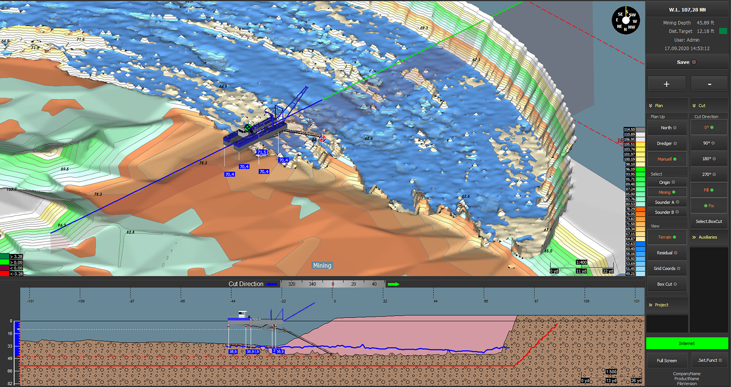
Thus, effective training and tools increase
production. It is possible for young
unexperienced employees to learn faster
with a real-time monitoring system, because
they see what they are doing and how much
progress they are making. They can literally
see their efficiency with one view in the
dredge-monitoring software (see Figure 2 for
an example).
Real-time monitoring also results in safer operation by reducing risk of slip-back and slope failure.
In addition, with fewer workers, contractors
struggle to perform the same (or more) work to
the expected quality standards. As a result,
innovators are looking to reduce the number of
workers required to do the job. By automating
some dredging functions, such as vessel
repositioning and anchor management,
workers can instead focus on tasks requiring
human judgement and intervention.
In the future, autonomous dredging may
become practical, akin to autonomous ferry
operation and container-vessel trials
currently under way. Autonomous dredging
would require skilled operators who are
comfortable with the technology involved in
offsite remote real-time dredge monitoring.
Benefits of real-time dredge monitoring
There are several benefits to monitoring
dredges in real-time. These benefits
include increased operator confidence,
lower hydrographic-survey costs, accurate
records of work performed, increased
production, safer operation, reduced
greenhouse gas emissions and improved
fleet-asset utilisation. Operators gain
increased confidence through the use of
the visualisation software as they can see,
based on actual soundings, what work has
been completed.
If the dredge is outfitted with accurate sonars,
sound-velocity and motion sensors, as well as
accurate positioning equipment to fix and
orient the dredge, daily surveys can be
eliminated. Not only are project costs lowered,
but the project manager also has accurate
records of work performed. This record may
prove useful for verifying performance to the
client, even if local currents carry sediments
back into the dredging area later.
Real-time dredge monitoring reduces the
frequency of repositioning the dredge for
rework. If the operator knows the area has
been dredged to design by actual soundings,
the operator can advance the dredge to the
next area. This avoids having to stand by for a
survey and if the survey results are not good,
having to rework the previous position
Real-time monitoring also results in safer
operation by reducing risk of slip-back and
slope failure (North, 2022). Safety is of
particular concern at port-deepening projects
where the slope under existing berth decks
was designed for shallower depths, or when
shipping channels are being widened
(Stainer et al., 2019).
Efficient dredging produces lower greenhouse
gas emissions from optimised diesel engine
run-time. For the foreseeable future, until
alternative fuels become commonplace,
dredges will operate on diesel. Efficient
dredging without rework reduces both excess
emissions and fuel costs.
When a dredging contract is executed on time
and on budget, without extended time on site
for rework, the contractor can commit that
dredge to follow-on contracts. Knowing the
asset can be deployed to a new project on time
is vital when contractors have their reputation
on the line.
Acoustic sensor options
A key piece of equipment in real-time dredge
monitoring is the acoustic sensor. Four types
of acoustic sensors can be used to obtain
soundings: single-beam echo sounders,
split-beam echo sounders, dual-axis sonars
and multibeam echo sounders. Each have their
own advantages and disadvantages.
Single-beam echo sounders
Single-beam echo sounders are low-cost
sonars, available in wide-beam or narrow-
beam versions. However, they produce
downward soundings only. They do not provide
area coverage, merely point soundings. To be
of value to the operator, multiple sensors must
be installed on a dredge to get sufficient data
points of the seabed. Thus, system cost
scales with the number of sensors employed.
In addition, single-beam echo sounders do not
cover the worked area until the dredge has
moved forward to the worked area. As one
operator commented, they only know what
they dredged four hours later and then they
must still reposition the dredge and do
the rework.
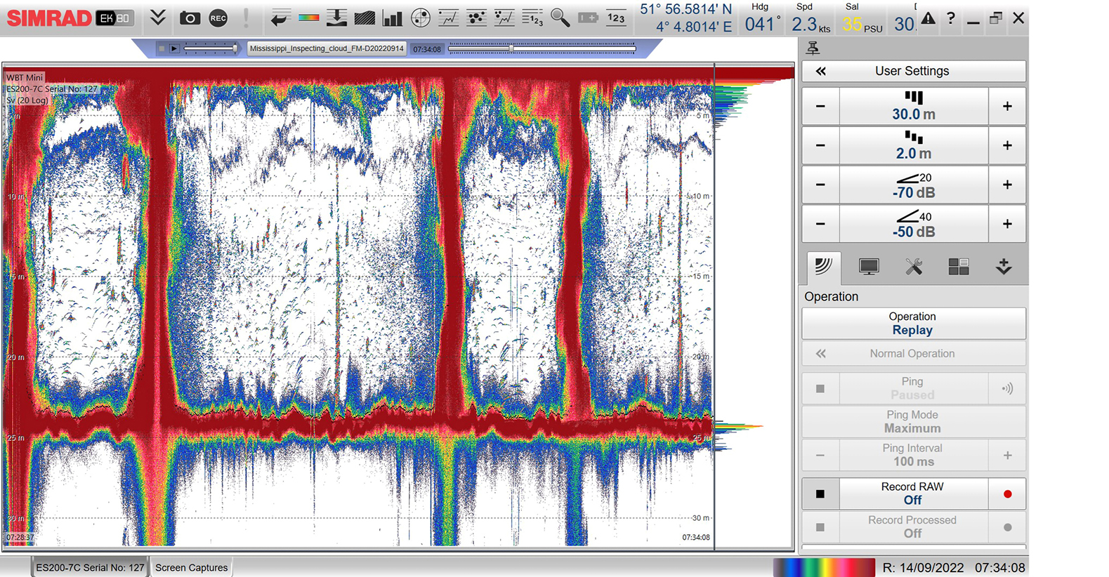
Split-beam echo sounders
Whereas single-beam echo sounders provide
no information on target location, split-beam
echo sounders use multiple transducers to
cover a larger area and calculate target
location in three dimensions. Split-beam echo
sounders can therefore detect solids
throughout the water column, quantify the
amount and density of solids, and quantify
what the material is.
With this functionality, the potential for
split-beam echo sounders in real-time
turbidity monitoring is promising. Split-beam
echo sounders have already been successfully
used to identify targets in the water column in
other similar applications. For example, by
ocean scientists to study biomass and in the
Gulf of Mexico to quantify hydrocarbon seeps
The use of split-beam echo sounders
for sediment detection is still being studied,
but proof of concept is not far behind.
Kongsberg’s Frank Reier Knudsen conducted
a preliminary feasibility study to determine
whether split-beam echo sounders can
detect sediments in the water column, with
good results.
Furthermore, preliminary controlled
environment studies in an outdoor tank by
Deltares and Ifremer indicate that split-beam
echo sounders have potential to show
sediment plume density, shape and rate of
dispersion. Preliminary field work by Boskalis
shows that a split-beam echo sounder can
track and quantify resuspended sediments in
an open water column, even in the presence of
background sediments (Mech, 2023).
As mentioned above, the type of bottom and
amount of turbidity may determine whether
you pick a high- or low-frequency sonar.
Split-beam echo sounders sweep through the
broad band transmit frequency and by using
different bands, the back-scatter amplitude of
the returned signal allows users to quantify
the amount and density of solids, and to
quantify what the material is.
If mitigating turbidity is a major concern,
split-beam echo sounders may be worth
considering when putting together a real-time
monitoring system. Understanding how much
(and where) sediment is being transported and
resettled is important, especially if there is
concern of industrial pollutants or
contaminants being transported downstream
The benefit of all these acoustic-sensor options is that they reduce the amount of rework required.
Dual-axis sonars
A dual-axis sonar is comprised of a single
narrow-beam transducer mounted on a
precise two-axis rotator. The transducer is
safely housed inside an oil-filled acoustically
transparent dome, which isolates the
transducer from the environment. A dual-axis
sonar produces point-cloud data similar to a
multibeam sonar. These soundings can be
integrated into post-processing software,
such as QPS Qinsy, Hypack, EIVA or Sonarwiz.
The operator can select the best area
coverage for a particular dredging site by
adjusting the step pitch between pings to gain
a fast, coarse measurement or a fine
measurement over more time.
For example, a pitch of 7 degrees between
pings provides 26 soundings in a 180-degree
arc, while a pitch of 0.2 degrees provides
900 soundings in that same arc. Crucially,
these soundings cover the area around the
loosening tool, allowing for rework before
the dredge is moved forward to advance
the operation.
It is pertinent that the ASCE Manual of
Practice 156 (Navigation Channel
Sedimentation Solutions) speaks to the
importance of field observations when
developing models of sediment behaviour in
shipping channels. Dual-axis sonars are
emerging as a useful tool for collecting these
field observations. Of particular importance is
slope stability during and after deepening
dredging for acceptance of larger vessels at
existing berths.
Dual-axis sonars are steadily replacing
single-beam echo sounders as the acoustic
sensor of choice in real-time monitoring
solutions. This fact is reflected in the fact that
several of the case studies presented here
use a dual-axis sonar.
Multibeam sonars
Multibeam sonars are available in imaging and
point-cloud versions. Some multibeam sonars
perform both functions in same sonar head.
For dredge monitoring and visualisation, users
should select point-cloud function sonars.
The main advantage of multibeam technology
is speed. Multibeam sonars can provide
soundings rapidly in a single sweep of the work
site. Similar to dual-axis sonars, the soundings
can be integrated into post-processing
software, such as QPS Qinsy, Hypack, EIVA or
Sonarwiz. However, processing the soundings
causes a delay to visualising work progress.
Multibeam systems require a single or
dual-axis rotator to sweep the beams over
the work area. However, more moving parts
means more potential points of failure and
maintenance to address seal wear. They can
be more susceptible to damage depending
on the dredge type. Therefore, extra
precautions must be taken to protect these
systems from transducer damage due to
solids in the water column.
Good-better-best
One framework to consider when deciding
what level of instrumentation is appropriate
for dredge operations is Good-Better-Best.
These acoustic sensors run on a price-
performance continuum where single-beam
echo sounders are most economical, split-beam and dual-axis sonars are more
expensive, and multibeam systems are most
expensive. As the systems increase in
performance and capability, the cost of
ownership also increases due to maintenance
and spares.
Regardless of which system is used, the
benefit of all these acoustic-sensor options
is that they reduce the amount of rework
required by providing the operator with
actual dredging performance, rather than
imputed performance derived from
inaccurate assumptions.
Case study 1: Cutter-suction dredge for maintenance dredging
In this case study, the sonar is mounted on the
front of the dredge, so the beam pattern
covers the area swept by the dredge as it
pivots on its spud. The operator has a
touchscreen in the cabin, which is used to run
the sonar and see progress of the removed
material to the design horizon.
Operators have found that relying only on
the inclinometer readings to show dredging
progress almost always showed more
material dredged than was actually removed.
As mentioned above, up to 20% of solids
disturbed by the loosening tool resettle back
onto the seabed. This resettlement can be
clearly seen in the side elevation view shown
in Figure 2.