Sediment erosion is a phenomenon of mechanical wear of components that decreases efficiency and uptime of the dredging process. Dredge pumps are designed to handle mixtures of water and solid particles with varying particle size from less than 0.002 mm to greater than 200 mm. A dredge pump’s overall effectivity in the field depends upon its uptime. Uptime is influenced by the number of times the pumping process is interrupted, which can be due to maintenance combating the material loss, clogging, etc. This research deals with the erosion phenomena by considering a framework of numerical models, capable of qualitative and quantitative erosion estimation, coupled with experiments for validation. Coordinate Measurement Machine (CMM) is used for surface roughness measurement before and after the experiment, thus depicting the material loss due to erosion.

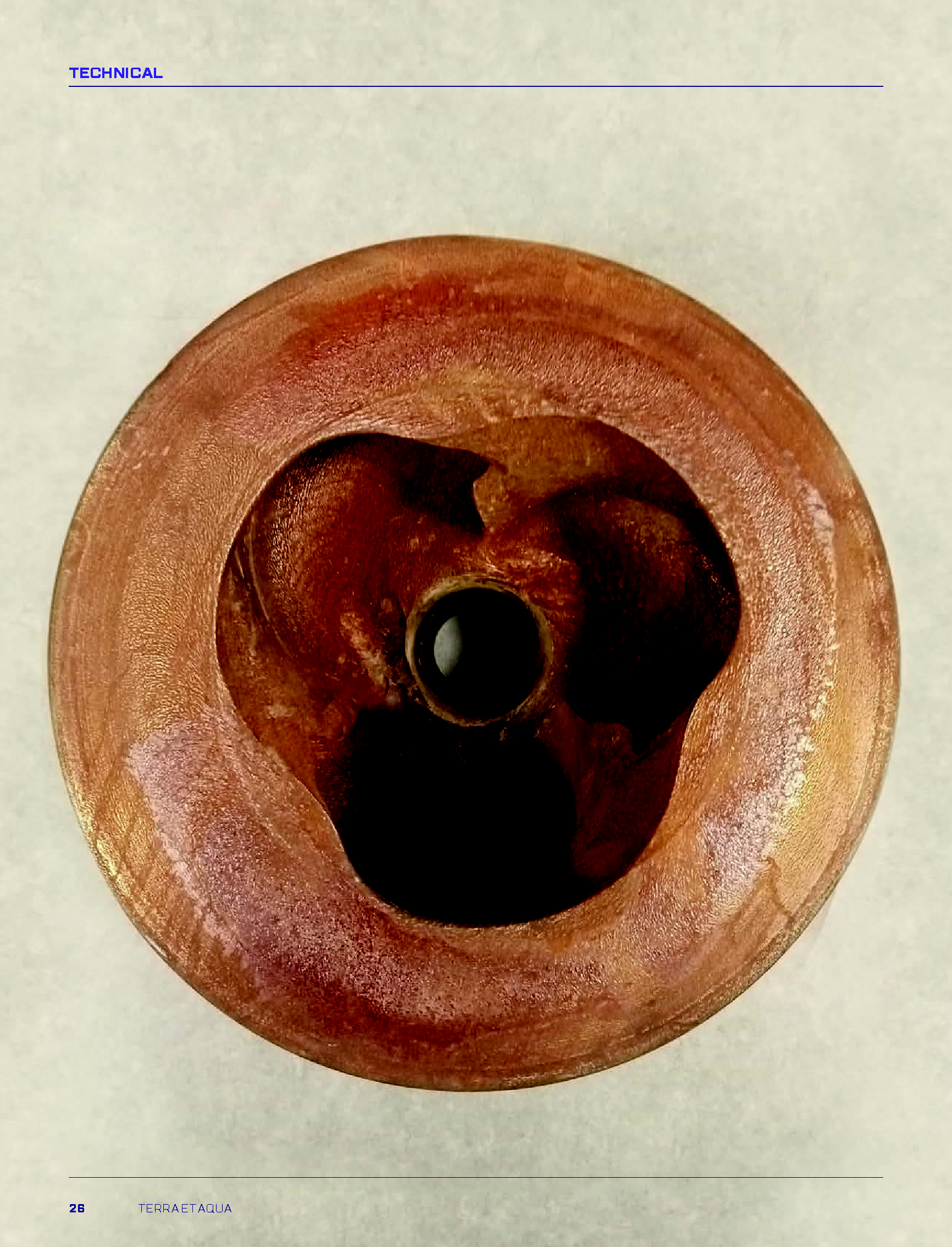
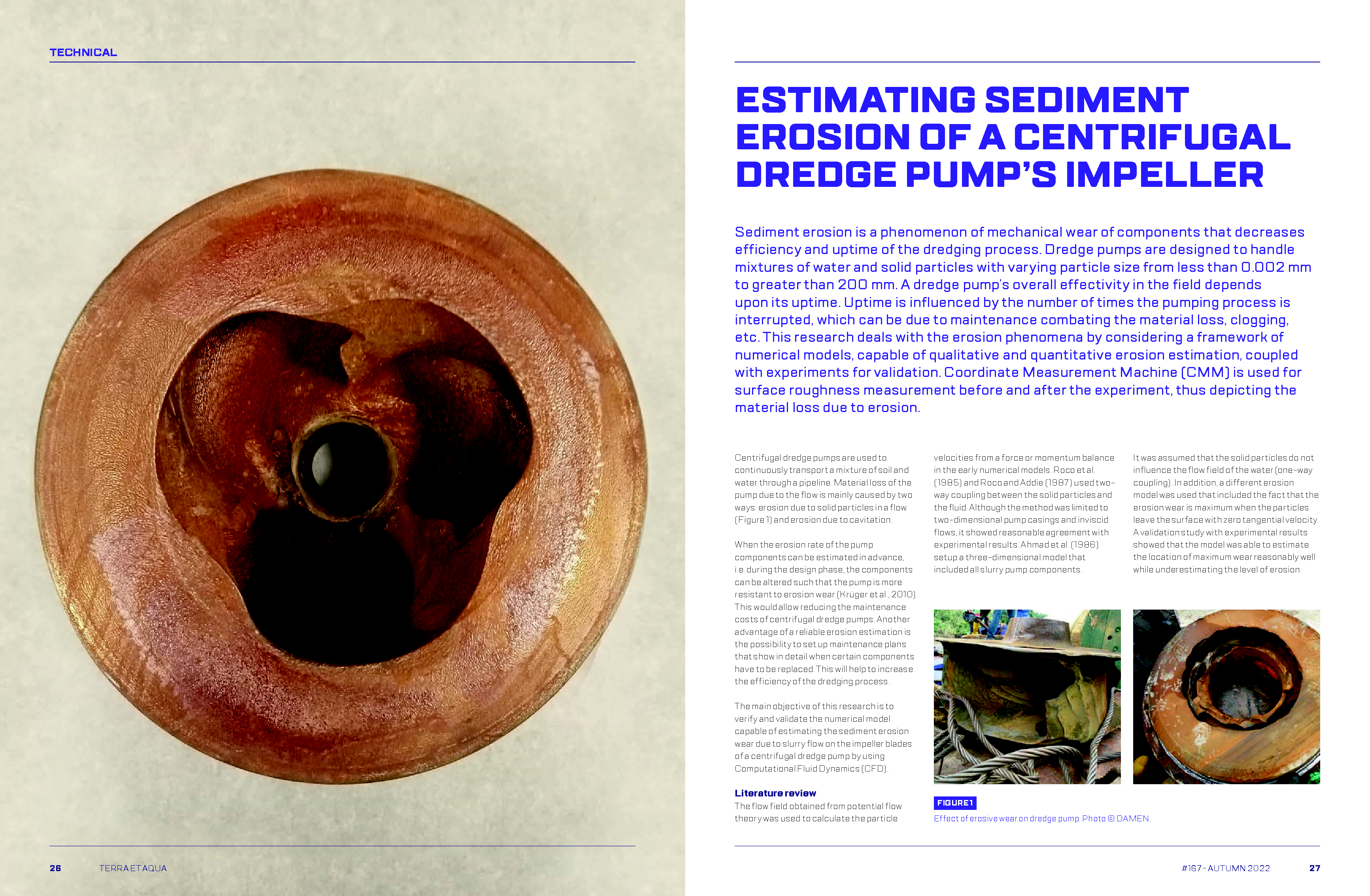
Centrifugal dredge pumps are used to continuously transport a mixture of soil and water through a pipeline. Material loss of the pump due to the flow is mainly caused by two ways: erosion due to solid particles in a flow (Figure 1) and erosion due to cavitation.

When the erosion rate of the pump components can be estimated in advance, i.e. during the design phase, the components can be altered such that the pump is more resistant to erosion wear (Krüger et al., 2010). This would allow reducing the maintenance costs of centrifugal dredge pumps. Another advantage of a reliable erosion estimation is the possibility to set up maintenance plans that show in detail when certain components have to be replaced. This will help to increase the efficiency of the dredging process.

The main objective of this research is to verify and validate the numerical model capable of estimating the sediment erosion wear due to slurry flow on the impeller blades of a centrifugal dredge pump by using Computational Fluid Dynamics (CFD).

Literature review

The flow field obtained from potential flow theory was used to calculate the particle velocities from a force or momentum balance in the early numerical models. Roco et al. (1985) and Roco and Addie (1987) used twoway coupling between the solid particles and the fluid. Although the method was limited to two-dimensional pump casings and inviscid flows, it showed reasonable agreement with experimental results. Ahmad et al. (1986) setup a three-dimensional model that included all slurry pump components.

Figure 1

Effect of erosive wear on dredge pump. Photo © DAMEN.

It was assumed that the solid particles do not influence the flow field of the water (one-way coupling). In addition, a different erosion model was used that included the fact that the erosion wear is maximum when the particles leave the surface with zero tangential velocity. A validation study with experimental results showed that the model was able to estimate the location of maximum wear reasonably well while underestimating the level of erosion.

More recently, Computational Fluid Dynamics (CFD) opened the doors for more sophisticated methods. Krüger et al. (2010) used an unsteady Eulerian-Eulerian model and found that the leading edge of the impeller blade suffers from erosive wear, with the maximum erosion in the middle of the leading edge. This was found to be due to the high turbulent kinetic energy close to the hub and shroud plates, which pushes the particles to the center. Along the blade, at the trailing edge and the side plate, abrasive wear dominates. To predict these phenomena accurately, it is important to accurately capture vortices and secondary flow structures in the impeller. Sapkota (2018) confirmed the occurrence of erosive wear at the leading edge and abrasive wear along the blade and near the trailing edge. In his study, based on a one-way coupled Eulerian- Lagrangian method in combination with Finnie’s erosion model (Finnie, 1960), it was found that the maximum erosion occurs at the leading edge and on the pressure side near the trailing edge. When the flow rate is increased, the erosion on the blades also increases. Moreover, recirculation zones lead to an increased probability of particle impact. For further studies, the research recommended improving the model by using four-way coupled simulations.

Figure 2

Schematic overview of the numerical models. The dashed part of the figure is only included for the two-way and four-way coupled methods.

Lai et al. (2018) found that an increase in concentration increases the erosion rate, due to particle impact frequency. On the other hand, it was shown that the particle diameter does not influence the particle trajectory and the impact frequency. These results came from computations with a transient two-way coupled Eulerian- Lagrangian model in combination with the E/CRC erosion model (Zhang et al., 2007). The transient nature of this model enabled it to show that the erosion rate first rises until a constant value is reached after about 0.5 seconds. Huang et al. (2019) confirmed the occurrence of the steady-state erosion rate using a similar model except for the erosion model. However, they showed that the time after which it is reached depends on the flow rate through the pump: for lower flow rates, the steady-state rate is reached later. Although Lai et al. (2018) showed that the particle diameter does not influence the particle trajectories, Tarodiya and Gandhi (2019), using a two-way coupled Eulerian- Lagrangian model, found that larger particle size are subjected to higher kinetic energy, thus, increasing the erosive wear. In addition, they found that increasing the concentration of the sand particles increases the wear, and lowering the pump speed leads to a reduction in wear.

Xiao et al. (2019) accounted in their study the change in geometry of the blade profiles due to wear by using a two-way coupled Eulerian- Lagrangian model. Qualitatively, the results of this model agreed with experiments, which were part of the study. By taking the geometrical changes into account, the unsteady behavior of the problem could be studied. This showed that the impeller blade degrades first, which enhances recirculation. Due to a combination of this recirculation and increased clearances, the wear at the impeller outlet, the bottom of the impeller blade and the volute casing decrease. Therefore, they concluded that small geometrical changes (for instance, due to erosion wear) change the later erosion patterns.

Several studies have already been conducted on the subject of erosion modelling for centrifugal dredge pumps. It was found that CFD can be used to compute the erosion pattern in a qualitative way (Krüger et al., 2010; Tarodiya and Gandhi, 2017), whereas the existing methods lack accuracy on a quantitative level.

Numerical model

The erosion occurring in centrifugal dredge pump impellers is modelled using the CFD package ANSYS Fluent version 2020 R2.

Water flow field

Following the Einstein convention, the governing equations (continuity and momentum) of incompressible flows after applying the Reynolds decomposition are given below (Nieuwstadt et al., 2016).

Here is the fluid density, is the averaged ensemble of the fluid velocity vector. For the turbulence equations, the SST turbulence model is used. The right side of the equation consists of the isotropic stress due to the mean pressure field , the mean body force , viscous stress and averaged Reynolds stress tensor due to the fluctuating velocity field, respectively. There are various turbulence models available to convert the Reynolds stress into mean quantities and ensure closure.

SST turbulence model (Menter, 1994) is followed in the current study based on the study from Wang and Wang (2012) and Ilker and Sorgun (2020).

Particle flow field

After obtaining the converged fluid flow field, the particle flow field is calculated using Newton’s second law for sets of particles, named parcels.

is the mass of the particle, equal to . In addition, the subscript refers to the vector component according to the Einstein notation and the subscript is used for quantities related to the particle. The terms on the right-hand side represent the forces acting on the particle.

The first force that is considered here is the drag force (ANSYS Inc., 2020a).


is the projected area of the particle normal to the flow (equal to ). In addition, the term is the drag coefficient, for which various models exist. For smooth, spherical particles, a general law called the Spherical Drag Law can be used (ANSYS Inc., 2020a):

is the particle Reynolds number and are the constants that have to be determined empirically.

The buoyancy force due to the difference in the density of the particle and fluid is given by (ANSYS Inc., 2020a):

is the volume of the particle.

When the particle accelerates through a fluid, a portion of the fluid is accelerated with it. This can be modelled as an additional mass that is quantified by virtual mass force (Andersson et al., 2012):

For the fluid acceleration, the substantial or Lagrangian derivative should be used (Crowe et al., 1998). The virtual mass factor is often set equal to 0.5.

Equation 8 quantifies the pressure force acting on the particle. It is assumed that the pressure and shear stress do not change over the volume of the particle (Andersson et al., 2012).

The rotational forces arise from rotating frames of reference (ANSYS Inc., 2020a). It includes the Coriolis (first term) and centrifugal forces (last term) and it correlates to (Sapkota, 2018):

In this equation, is the position vector. In the current study, the Discrete Random Walk model is adopted for the turbulent dispersion force.

Particle-wall rebound

Grant and Tabakoff (1975) proposed an empirical model for the restitution parameters () (ratios of normal (subscript ) and tangential (subscript) velocities before and after the collision) with a dependency on the particle impact angle (α in radians).

Particle-particle interaction

By using an additional extension of the model, the four-way coupled method is obtained. Here, also the forces due to inter-particle collisions are taken into account when calculating the particle flow field. This is done using the linear soft sphere collision model (also known as the DEM model). In this model, the forces in normal and tangential directions are split. In the normal direction, the collision is modelled as a spring system. This spring system can either be linear or non-linear. For the former, the force induced by the collision is equal to (ANSYS Inc., 2020a):

In this equation, is the spring constant, is the overlap of the parcels (or particles) and is the fraction of the diameter that is allowed to overlap. In addition, is the diameter of the colliding parcels and is the unit vector between the two colliding parcels (or particles). In tangential direction, Coulomb’s friction law gives (ANSYS Inc., 2020a):

In Equation 13, the friction coefficient  has to be determined through literature or experiments.

Erosion model

The Oka erosion model is used which takes into account the impact angle α, particle size, material hardness, and velocity of the individual parcels hitting the target surfaces (Oka et al., 2005a). The model calculates the erosion rate in terms of volume from the same erosion rate at an impingement angle of 90 degrees.

This impact dependent function includes two coefficients ( and ) and the material Vicker’s hardness . The coefficients themselves also depend on the hardness of the target material (Oka et al., 2005a). In this equation, the constants , and depend on the particle properties, whereas is determined both by the material hardness and the particle properties. Moreover, and are empirical coefficients. The quantities and are the standard impact velocity and the particle diameter, which were used in the experiments for the determination of the erosion correlations (Oka et al., 2005b).

Experimental setup

For the experiments, a facility is used that is operational and available with the company Damen Dredging Equipment. This circuit is known as the “test loop” and can be seen in Figure 3.

Starting from the dredge pump (Figure 3), the mixture flows through the vertical U-bend and a horizontal 180-degree bend. After encountering a long horizontal pipe and another 180-degree bend, the flow enters a section with a density and a flow meter.

During the erosion experiment, Dredge Gate Valve 2 (DGV2) is closed, which allows the mixture to flow directly back to the dredge pump. Therefore, during the experiments, the circuit is a closed-loop system. When DGV2 is opened, the mixture can be forced through the hopper or the dump pipe that allows the user to control the sand concentration within the circuit. Since the conditions used by Sadighian (2016) are similar to the conditions in the current study, it is expected that, by refreshing the sand about every 9 hours, the effect of particle degradation is minimised.

Table 1

Parameters for the experiment. *Time to start and stop the system are not taken into account.

Erosion measurement

For the quantification of the erosion wear, a Coordinate Measurement Machine (CMM), CRYSTA-Apex S1200 series model, is used. This device measures the x-, y-, and z-coordinates (relative to a reference frame defined on the object) of discrete points that are located on the surfaces of the measured object (Keyence Corporation, 2021). These points can either be measured using a contact probe or an optical probe. The theoretical accuracy of the machine is defined as is a measure for the size of the object in millimeters. In practice, the accuracy also depends on factors related to the state of the object, such as the roughness. Therefore, the practical accuracy will generally be lower than its theoretical counterpart () (Mitutoyo Corporation, 2021).

The thickness loss due to erosion wear at the different measurement points can be found by comparing the CMM measurements of the impeller before and after the wear experiment. For this, the CMM can be programmed such that it measures the same profiles during both measurements. A limitation associated with the CMM was that it was not able to measure the entire blade due to the absence of a longer optical probe. More specifically, the leading edge and a part of the suction side of the blade are not included in the experimental erosion results as the shorter contact probe was not able to measure the areas close to the aforementioned surfaces. In addition, the parts of the blade that are close to the hub and shroud of the impeller are not measured.

Results

Benchmark study: Impinging jet

Two separate studies are used for the benchmark study and thus two sets of grid independent studies for flow field and erosion validation respectively. The fluid and particle flow fields are validated using the experiment by Miska (2008), whereas the validation of the resulting erosion pattern is performed using the research conducted by Wang et al. (2021) (Figure 5). For measuring the velocity field, the Laser Doppler Velocimetry (LDV) technique was adopted by Miska (2008).

Since the flow rate through the nozzle is known, a constant velocity is specified at the inlet of the nozzle by using a “velocity inlet” boundary condition. The inner and outer sides of the nozzle, as well as the target surface, are described by the “no-slip wall” boundary condition. The part of the outer diameter that is closest to the wall is defined as a “pressure outlet”, whereas for the remaining sides of the domain the “pressure inlet” boundary condition is used to allow for entrainment.

Flow field validation

The first step in the validation of the fluid flow field consists of a grid convergence study. For quantifying the grid convergence, the pressure averaged over the target surface is used as the scalar quantity. From this quantity, calculated for the three finest grids, an observed order of accuracy equal to 1.7 was obtained (Celik et al., 2008).

In Figure 6, the fluid flow fields as calculated with the four grids are compared with the experimental results of (Miska, 2008). This is done using the velocity profiles at four different locations as indicated by red lines. When comparing the numerical to the experimental results, the top two graphs in Figure 6 show that the axial velocity in the middle of the jet is computed accurately. In addition, in Figure 7 (bottom right), it can be seen that the numerical radial velocity profile away from the center of the domain is close to the experimental profile. On the other hand, directly behind the nozzle wall, the axial velocity is overpredicted, especially near the sides of the profile. In addition, in line with the nozzle wall, there is a noticeable difference between the numerical and experimental profiles for the radial velocity due to the highly curved streamlines in that region.

Figure 3

The “test loop” facility with 3D-model and cross-section of the centrifugal dredge pump (top right) and impeller (below).

Figure 4

Coordinate Measurement Machine (Mitutoyo Corporation, 2021)

Figure 5

Left: Experimental setup for the submerged impinging jet as used in the study of Miska (2008). Centre: Cross-section of the computational domain for the flow field benchmark. Right: Experimental setup for the submerged impinging jet used in the study of Wang et al. (2021).

Table 2

Specifications for the benchmark study.

Influence of the particles on the water flow field

In the second phase of the experimental study by Miska (2008), the small particles ( diameter) were replaced by aluminum particles with a mean diameter of .

The first step in the validation of the particle flow field is to verify whether these results converge to a certain solution while refining the grid. By comparing the numerical to the experimental results, it turns out that the axial and radial particle velocity is overpredicted and underpredicted respectively (Figure 7). The latter is caused by the underprediction of the radial water velocity at those locations.

Erosion validation

In the second part of the benchmark study, the numerical erosion is compared to the results of the experiment conducted by Wang et al. (2021). Since the domain of Wang et al. (2021) is slightly different, there is a need for another set of grid convergence studies. For the next set of grid convergence tests (Figure 8), the order of accuracy was found to be 1.8 for the average pressure around the target surface (Celik et al., 2008).

The erosion is quantified in terms of the thickness loss rate in . The x-coordinate is non-dimensionalised by using the radius of the nozzle. Since the increase in computational effort of grid 4 with respect to grid 3 is considerable, grid 3 is considered to be sufficiently refined. Therefore, this grid is used for the comparisons in the following paragraphs.

Figure 6

Comparison of the numerical results, as computed using different grids, with the experimental fluid velocity field for different profiles (Miska, 2008). The red lines indicate the locations of the velocity profiles.

Figure 7

Comparison of the two-way coupled numerical results, as computed using different grids,

The minimum amount of erosion can be found directly in line with the centerline of the nozzle. This is due to the particle velocity being (almost) equal to zero as was also demonstrated for the flow field benchmark. When moving away from the center of the target surface, the erosion rate increases until it reaches its peak around . This implies that the erosion peak occurs outside the nozzle diameter projected on the target surface.

The magnitude of the erosion peak is largely overpredicted. For the specific type of stainless steel that was used by Wang et al. (2021), hardness values as high as 3.687 GPa can be found. In Figure 9, the resulting erosion profile for this hardness is compared to the erosion profile obtained with a hardness equal to 1.795 GPa. Although the larger hardness still involves a certain error, changing the hardness does have a significant effect.

Sensitivity tests: Coupling

In Figure 10, the erosion profiles for the different coupling methods are compared. In addition, to illustrate the dependency of the four-way coupled method on the parameters of the collision model, the resulting profile for this method is shown for two different values of the static friction coefficient .

While the profile for is closer to the one-way coupled result, the profile for is similar to the profile that is computed with the two-way coupled solver. This large difference can be attributed to the loss in kinetic energy of the particles due to the friction; for a higher friction coefficient, the velocity of the particles near the wall decreases considerably as compared to the situation with a small friction coefficient. For the four-way coupled solver to be accurate, the accurate values of the parameters from this collision model should be obtained (either from literature or from conducted experiments).

Sensitivity tests: Erosion model

To verify the choice of the Oka erosion model for this specific situation, a comparison is performed that includes the different erosion models, which is considered to have a similar performance as the Oka model (Zhang et al., 2007). In addition, the Finnie erosion model is included since this model is often used in literature.

Figure 8

Comparison of the erosion profile, as computed using the two-way coupled method for different grids, with the experimental erosion profile at the target surface (Wang et al., 2021). The center of the domain is located at .

Figure 9

Comparison of the erosion results, as computed using the two-way coupled method for different values for the hardness (Wang et al., 2021). The center of the domain is located at .

Figure 10

Comparison of the erosion results using the different coupling methods (Wang et al., 2021). The middle of the domain is located at .

Figure 11

Comparison of the erosion results, as computed using the two-way coupled method in combination with different erosion models (including the results of the experiments by Wang et al. (2021). The middle of the domain is located at .

For all the profiles, the erosion is the smallest in the middle of the target surface. The erosion rate increases until it reaches its peak around . This location is predicted well by all the considered erosion models. Quantitatively, however, there are large differences between the results. Finnie’s model does not take into account the size and shape of the solid particles. This introduces additional uncertainties in the model. For the E/CRC model, similar reasoning can be given as for the Finnie model. Zhang et al. (2007) showed that the parameters that are used in the E/CRC model were developed with experimental data using the material Inconel 718 and do not take into account the diameter of the particles.

Impeller model

Verification

By making use of the symmetry within the impeller, only one of the three blades is included. To this end, two periodic faces are defined with a rotational symmetry boundary condition. The domain contains four different walls, the hub, the shroud, the blade and the pipe (all walls are defined with the no-slip condition). In addition, the flow enters the pipe through a velocity inlet condition and exits the impeller via a pressure outlet. The impeller walls rotate with the same rotational velocity as the domain. For this, the computational domain is displayed in Figure 12.

For the grid convergence study, three different grids are constructed that are geometrically similar. For this, the parameters that are listed in Table 3 are used. It can be seen that for all three grids, the first cell height is larger than the particle diameter that is used in the computations. This results in a for all three grids within the range of the applicability of wall functions. Although flow separation is expected to occur from the impeller blades, it is not possible to refine the near-wall region further, since this would compromise the computations of the particle paths. In Figure 13, the different grids around the impeller blades on a y-z plane are displayed.

For the quantification of the grid convergence, the head of the pump can be used. This parameter is the total pressure difference between the outlet and the inlet of the impeller. The resulting relative error is displayed as a function of the typical cell size in Figure 14. Since the convergence of computations on the two finest grids is such that there is still a variation in the head of about 1%, the head that is used to calculate the relative error is averaged over the last 200 iterations.

To verify the grid convergence on a local scale, the pressure along the blade is shown in Figure 15.

Table 3

Grid parameters used in the grid convergence study for the impeller.

Figure 12

Numerical domain for the impeller computations.

Figure 13

Cross-section of the different grids that are used for the impeller grid convergence study.

In Figure 15, the position on the blade is nondimensionalized using the chord length(c) of the blade. Therefore, the leading edge can be found at , whereas the trailing edge is located around . It can be seen that the difference between the results becomes smaller with an increasing number of cells. However, the difference between grids 2 and 3 is still relatively large, which is also visible in Figure 15. From the discussion in this paragraph, it can be concluded that grid 3 is the best option to base the erosion calculations on. However, it turned out that on the two finest grids, the particle tracking computations using the two-way coupled method could not be converged. Therefore, in the following paragraphs, the coarsest grid is used.

Validation of the erosion model

In the previous section, a comparison between different erosion models is performed for the impinging jet benchmark. In this paragraph, the same analysis is done for the impeller. Here, erosion models like the Oka, Finnie and the E/CRC are compared with the experimental results. Only the part of the blade where the erosion was measured is shown in Figure 16.

It can be seen that the erosion values predicted by the E/CRC model are much larger than those for the experiment as well as for the other erosion models. This large overprediction may be due to the fact that the model was designed for high particle velocities in combination with rather small particle diameters. In addition, the material that was used during the experiments was Inconel 718. Therefore, it may be that the applicability of the model is restricted to situations that are more similar to the design conditions than the conditions used in the current project.

The differences between the Oka and Finnie erosion models are much smaller. While there is a slight underprediction in Figure 16 of the erosion rate at the suction side of the blade by the Oka model, the Finnie model predicts a higher erosion rate than the experimental value at the same location. The reason for this is that the Finnie model predicts the maximum erosion for a lower impingement angle than the Oka model. This is visualised in Figure 17.

The erosion that occurs in the region that is shown in Figure 16 is mostly due to sliding wear corresponding to the study of Krüger et al. (2010). Therefore, the differences in results for the Finnie and the Oka erosion models are due to the different angle dependencies of the two models. In the specific profile that is shown in Figure 16, the Oka model is closer to the experimental results. However, in other regions, the Finnie model corresponds better to the experiment. Therefore, for the validated region, the models perform equally well. However, at regions where the impact wear is dominant (for instance at and near the leading edge of the blade) it is expected that the prediction of the Oka model is much closer to reality than that from the Finnie model. This is because the Finnie model yields an underprediction of the erosion rate for impact angles larger than 45 degrees. Moreover, Figure 17 shows that at a 90-degree impact angle, the Finnie model predicts no erosion at all. Therefore, it can be concluded that the Oka model is more suitable for computing the erosion in a centrifugal dredge pump impeller than the Finnie model.

Figure 14

Relative error (based on the head) for the impeller computation as a function of the typical cell size.

Figure 15

Comparison of the pressure distribution along the impeller blade for the different grids.

Figure 16

Erosion profile along the blade for different erosion models (including the results of the experiment. On the right-hand side of the figure, the definition of the curve length is shown.

Figure 17

Normalised erosion as a function of the impingement angle.

In Figure 18 and 19, the numerical and experimental results are compared. For the former, the two-way coupled method result on the coarsest grid (Table 3) is used. The suction side and trailing edge of the blade are shown in Figure 18.

When comparing the erosion values at the suction side of the blade, it can be seen that the erosion profiles correspond well qualitatively. The magnitude of the erosion increases when moving towards the trailing edge of the blade. In addition, the erosion increases in the direction of the shroud. Quantitatively, however, there is an underprediction of the erosion values at the suction side of the blade by the numerical model. One explanation for this would be that a constant particle diameter was used in the numerical model, while the PSD showed a large spread of particle diameters as used during the experiment. Since the gravitational acceleration acts in the positive x-direction, neglecting the smaller particles results in more particles moving towards the shroud. Especially since the densimetric Froude number for this situation is equal to 4.4, which indicates that the effect of gravity cannot be neglected. Another explanation would be that the recirculation zone that is causing the erosion at the suction side is smaller in reality than that is calculated. Since the recirculation zone is a complex phenomenon to capture, the strength of the vortices within the recirculation zone may be larger in reality than in the calculation. This leads to an underprediction of the impingement velocity and volume fraction at the blade.

The trailing edge of the blade shows that the erosion at that location is underpredicted. According to the numerical model, there is only erosion at the part of the blade close to the shroud, while the experiment showed erosion over the entire height (in the x-direction) that was measured. This discrepancy can be explained by looking at the fact that the flow separates from the blade somewhere at the trailing edge. Keeping in mind that the numerical model that is used in this study is not capable of calculating large separating flows, it cannot be expected that the model captures the flow well at that region.

Figure 18

Erosion pattern on the suction side and the trailing edge of the blade for the two-way coupled numerical model (left) and the experiment (right).

The third region that was measured during the experiments is the pressure side of the blade. The comparison between the numerical and experimental results for this side is shown in Figure 19. On the pressure side, only a small (relative to the erosion occurring at the suction side of the blade) amount of erosion was measured. This erosion region is missing in the numerical results. An explanation for this would be that the inter-particle collisions are neglected in the numerical model. These collisions enhance the turbophoresis effect (the tendency of the particles to flow towards the low turbulence level) and with that, the particles flux towards the wall. The fact that the erosion increases while moving towards the trailing edge supports this explanation, since the turbophoresis effect would also yield a positive volume fraction gradient (and with that a positive erosion gradient) in the flow direction.

Conclusions

It is found that for the conditions that typically occur in a centrifugal dredge pump impeller, the Eulerian-Lagrangian method is appropriate for modelling the slurry flow. The benchmark study with impinging jet showed that the fluid and particle velocities showed good correspondence with the experimental results. The largest deviation between the numerical model and the experiments could be found directly in line with the nozzle wall, which is due to the inability of the model to calculate the flow field at locations with large streamline curvature.

For the impeller model, it is found that the twoway coupled method provides significantly more accurate results than the one-way coupled method. A comparison between the different erosion models showed that the E/CRC erosion model overpredicts the erosion loss. In addition, the Finnie and Oka erosion models performed equally well for the validated region. However, due to the inability of the Finnie model to predict the erosion at and near the leading edge of the impeller blade, it can be concluded that the Oka model is the most suitable model for computing the erosion occurring in the centrifugal dredge pump impeller. A longer contact probe for the CMM machine would improve the validation of the numerical model since then the leading edge and suction part of the impeller could be measured and included in the analysis.

By comparing the numerical and experimental results (as calculated using the two-way coupled method), it is found that the erosion rate at the suction side of the blade is slightly underpredicted, while the results show good agreement qualitatively. For the pressure side of the blade, there are larger differences, although the major part of this side does not show any erosion at all for both the numerical and the experimental results.

Despite the modelling framework that contains many sub-models, limitations associated with the models are studied. The immediate takeaway from the study indicated the need to reduce the recirculation zone and smoothen the flow at the pressure side by correcting the flow incidence for the improvement in blade design. From the erosion study, it was found that more than 1 mm of material loss was seen in the suction side close to the trailing edge after the 55.7-hour experiment. This data is planned to be used for future research in the erosion analysis of the eroded geometry of the impeller. Future research to optimise the modelling framework for including for various working conditions, material, and sediment properties is expected to help set up a predictive maintenance plan for early detection of erosion problems.

Figure 19

Erosion pattern on the pressure side of the blade for the two-way coupled numerical model (left) and the experiment (right).

René Kolman, IADC’s Secretary General, presents the Young Author Award 2022 to Suman Sapkota for the co-authoring of his research paper, Estimating sediment erosion for centrifugal dredge pump’s impeller. The award is presented at industry-leading conferences, with this year’s winning author selected from the proceedings of WODCON XXIII, held in Copenhagen, Denmark, 16-20 May 2022.

Authors

Suman Sapkota

Trained as a mechanical engineer, Suman Sapkota works as a research, development and innovation engineer for Damen Dredging Equipment, in the Netherlands. He has a background in 3D modeling (CAD), computational fluid dynamics, finite element analysis and sustainable energy technology. Suman completed his MSc in sustainable energy technology (specialisation in engineering fluid dynamics) from the University of Twente, in the Netherlands. His specific research interests lie in fluid mechanics for turbomachines, cavitating flows, sediment erosion and fluid-structure interaction (FSI).

OTHER ARTICLES BY THIS AUTHOR
Wim Kleermaker

After gaining a BSc in Mechanical Engineering from HAN University of Applied Sciences, Wim Kleermaker obtained a master’s degree in Aerospace Engineering at Delft University of Technology, in the Netherlands. He graduated on the subject of dredge pumps at the company Damen Dredging Equipment. In 2021, he joined the Maritime Research Institute Netherlands (MARIN) as a project engineer/specialist. Within this role, his focus is primarily on performing numerical simulations for offshore applications.

OTHER ARTICLES BY THIS AUTHOR
Ruud A.W.M. Henkes

In 1985, Ruud Henkes obtained an MSc (Hons) in Aerospace Engineering from Delft University of Technology (TU Delft), in the the Netherlands. He gained a PhD (Hons) in fluid flow and heat transfer in 1990 at the same university. Associate Professor Aerodynamics at TU Delft until 1997, he then joined the multiphase flow team of the Shell Technology Centre in Amsterdam. Ruud has held various roles as team lead and principal technical expert (Fluid Flow) at Shell. Since 2008, he has combined a (part-time) full professorship in multiphase flow at TU Delft and as of 2021 holds the position of Scientific Director of the J.M. Burgerscentrum for Fluid Mechanics.

OTHER ARTICLES BY THIS AUTHOR
Alexander van Zuijlen

Alexander is Assistant Professor at the aerodynamics section of the Faculty of Aerospace Engineering, Delft University of Technology (TU Delft), in the Netherlands. He obtained his doctorate in 2006 from TU Delft on the topic of computational fluid-structure interaction. Alexander’s research focuses on development of numerical methods for multi-physics simulations and reduced order modeling for fluid-structure interaction applications.

OTHER ARTICLES BY THIS AUTHOR